Powerful equipment, flammable chemicals, and high-pressure processes can all easily lead to hazardous or even deadly incidents. The process industry, especially the oil, gas, and chemical sector, is hazardous, and it is crucial to ensure the safety of our assets and of our workers. Therefore, it is essential to identify and prevent potential hazards on site.
“Successful engineering is all about understanding how things break or fail.” ~ Henry Petroski, America’s failure expert
Many plants rely on Safety Instrumented Systems (SIS) to help address these potential failures to, in turn, prevent the hazards from occurring.(A hazard is a potential source of harm or adverse health effect on a person or persons.)
Safety Instrumented System (SIS)
To understand what a Safety Instrumented System (SIS) is and how it helps to prevent Hazards, we first need to understand the different Lines of Defence (LOD) / Layers of Protection (LOPA) and where Safety Instrumented Systems (SIS) fit in.
These Lines of Defence (LOD) / Layers of Protection (LOP) are independent layers that serve to either prevent an initiating event (e.g., loss of cooling) from developing into an incident (e.g., a release of a dangerous substance), or to mitigate the consequences of an incident once it occurs.
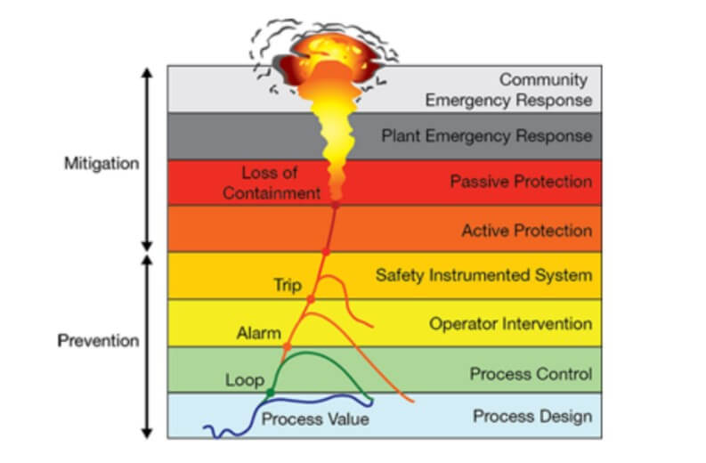
The first layer is the Basic Process Control System (BPCS). The Basic Process Control System (BPCS) controls pressure, level, temperature, flow, etc.
However, the problem is, Process Control Systems (BPCS) can fail! Designers and engineers cannot foresee every possible hazard and design control systems to prevent all of them. If so, we would not need alarm systems, relief valves, flares systems, etc. But since it is not so, process facilities need multiple layers of protection…
When a BPCS fails, the next layer of protection, after operator intervention, is the Safety Instrumented System (SIS), independent from the BPCS.
A Safety Instrumented System (SIS) does not control anything. It monitors many of the same variables as the BPCS but only takes action when a variable is outside its normal range, which generally means the Process Control System (BPCS) has failed.
Each SIS performs one or more Safety Instrumented Functions (SIF).
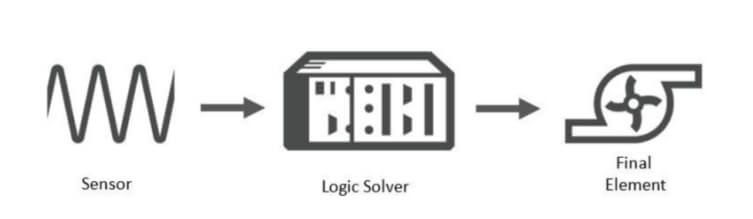
Safety Instrumented Function (SIF)
Safety Instrumented Functions (SIF) comprise three elements: sensors (e.g., a flowmeter) and logic solvers (e.g., a safety PLC) that detect dangerous conditions, and final control elements (e.g., a valve) that are manipulated to achieve a safe state.
Safety Instrumented Level (SIL)
Safety Integrity Level (SIL) indicates the degree of risk reduction provided by an Instrumented Safety Function (SIF) implemented by a Safety Instrumented System (SIS) within a given process. In other words, SIL is a measure of the SIF’s performance in terms of the Probability of Failure on Demand (PFD).
When designing a SIF, the appropriate SIL is crucial for achieving the required level of safety.
IEC 61508 defines four SIL levels, with SIL 4 providing the highest level of safety performance. For example, SIL 1 corresponds to a Risk Reduction Factor (RRF) of at least 10, and SIL 4 to a Risk Reduction Factor (RRF) of at least 10,000.
The table below shows the associated Average Probability of Failure on Demand (PFDAvg) and Average Risk Reduction Factors (RRFAvg) for each SIL.
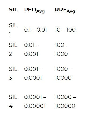
So, the higher the SIL level, the higher the associated safety level, and the lower the probability that a system will fail to perform. Normally, a higher SIL level means a more complex system and higher installation and maintenance costs.
Process plants typically only require SIL 1 and SIL 2 SIFs. SIL 3 and SIL 4 SIFs are very rare and normally not economically beneficial to implement since they require a high degree of duplication. In most of these cases, one should reconsider the fundamental design of the process.
Here it is also important to mention that SIL levels only apply to SIFs. Individual products or components do not have SIL ratings. However, they can be marked as suitable for use within a given SIL environment.
Functional safety standards: IEC 61508/61511
Let’s just talk a bit about the IEC 61508 and the other standards out there.
In 1998 the International Electrotechnical Commission (IEC) published IEC 61508, the first international standard to quantify the safety performance of an electrical control system and introduce the concept of the lifecycle. The main goal of this standard is to minimize the failures in all electrical/electronic/programmable electronic safety-related systems.
The IEC 61511 standard was developed as a process sector implementation of IEC 61508 and gives requirements for the specification, design, installation, operation, and maintenance of Safety Instrumented Systems (SIS).
In the U.S., ANSI/ISA-84.00.01 is used. This is the same as the international standard IEC 61511, with the addition of a grandfather clause to accommodate existing SIS installations.
These standards represent current good practices in the management of SIFs at process plants across the world. Adopting these standards will ensure suitable management of risk. Thus, SIL Assessment Software / SIL Calculation Software should also be aligned with these standards.
Calculating the Safety Instrumented Level (SIL)
To determine a SIF’s SIL level, the SIF’s overall PFD must be calculated. This SIL calculation basically combines the Failure Rate data for each of the individual SIF components (i.e., the sensors, logic solvers, and control elements) and accounts for test frequency, redundancy, voting arrangements, etc.
Failure Rate data for each component can be obtained from the equipment manufacturers. But, even with this available, the calculation is quite sophisticated. Therefore, it is recommended to use good SIL assessment software / SIL calculation software to determine the SIL. Also, user competency and experience are essential, and the input of many disciplines is required.
But how does the SIL calculation fit into the bigger picture? For that, we need to understand the Safety Lifecycle.
Safety Lifecycle
The IEC standards define a concept known as the Safety Life Cycle. This is a cyclic process where all hazards are identified and analyzed to understand which hazards require an SIS.
The Safety Lifecycle can be outlined in a few steps to show where the SIL calculations fit in:
- First, identify the hazard and its frequency.
- Determine if this frequency is acceptable (with no SIS). If so, no SIS is needed, else:
- Determine the hazard’s SIL level by calculating the target RRF of each SIF. Determine the SIF’s minimum RRF.
- This is the hazard’s frequency (without SIS) divided by the acceptable frequency. When the minimum RRF is known, the SIF’s target SIL level can be obtained from the SIL table. SIFs may have different target SIL levels.
- Design an SIS so that each SIF has a PFD corresponding to the target SIL level.
- The SIF’s overall PFD is determined with SIL calculations. The SIF’s RRF can then be compared to the minimum required RRF (remember RRF = 1/PFD.). If greater than the minimum required RRF, the SIF is sufficient.
SIL determination requires care. Thus, one should also take care when choosing SIL assessment software / SIL calculation software. Ideally, the software should not only focus on the SIL calculation but assist with the whole Safety Lifecycle analysis.
Has this sparked your interest?
You can use the form below to book a demo directly and see our solutions in action.

Elsa Tolsma-de Klerk Technical Writer
Elsa is an engineer with a passion for sharing knowledge. She holds a Master’s in Electronic Engineering and spent over a decade at Sasol as an Advanced Process Control Engineer, where she gained hands-on experience in optimization, control systems, and writing technical documentation. Since 2019, she’s been a Technical Writer at Cenosco, now leading the Product Knowledge Management and Academy team.