Two of the main goals of HSSE (health, safety, security, and environment) programs in oil and gas are to eliminate leaks and prevent costly interruptions to throughput. To achieve these goals pressure equipment (boilers, heat exchangers, tanks, etc.) management programs rightfully get significant attention due to potentially catastrophic health and environmental effects and impacts to productivity when equipment fails.
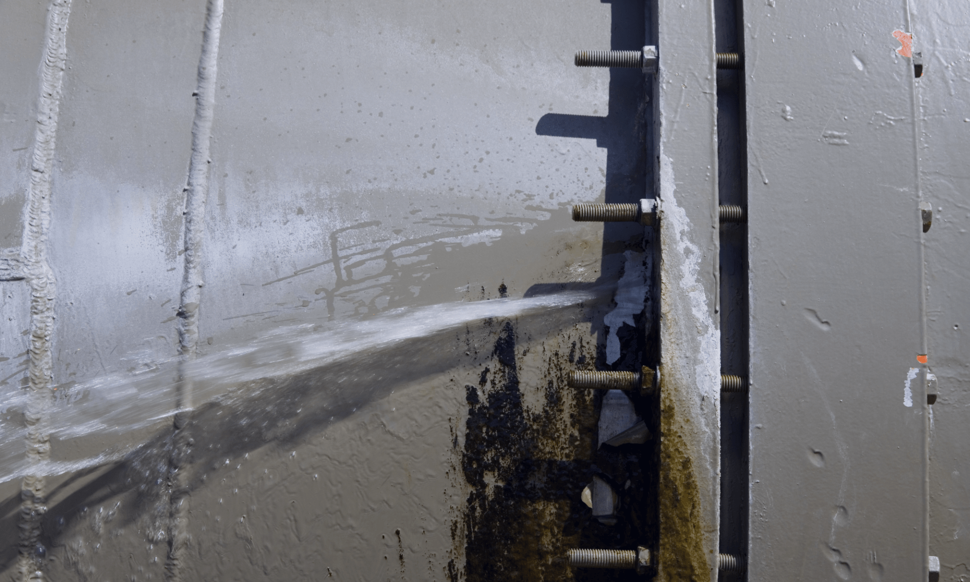
No less important are the flange connections between each of those pieces of equipment. Even a moderately-sized facility can have tens or hundreds of thousands of flange connections, each operating under widely varying physical conditions. From experience, we know that they are a significant source of losses of primary containment (LOPC), and, as a result, are the cause of significant risk to human health and the environment.
We’ll talk about how to manage those flanges in a minute, but first, let’s consider how they fail and prevent leakage.
How do Flanges Fail?
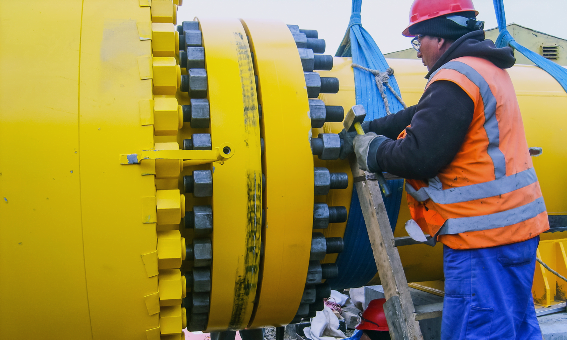
When we talk about flange connections, most often we’re referring to two types of connections. The first, flanges, are circular, bolted connections between pieces of equipment with a gasket or seal sandwiched in between. The second, clamp connectors, (commonly known as Grayloc connectors) rely on a clamp to provide compression to a seal ring located between the connection.
In both cases, compression of the seals or gaskets helps pressure and prevent fluids from leaking. Below we highlight a few of the potential failure methods for both types of connections:
- Improper Installation: Improper alignment, material selection, and bolt tightening can lead to uneven compression of gaskets and seals, or even gaps between the two sides of the connection, leading to leaks.
- Worn or Damaged Seals: Over time, seals used in flange connections can degrade or develop cracks, compromising their ability to create a seal. Additionally, improper handling or installation of gaskets can cause damage and improper installation, leading to leaks.
- Improper Bolt Torque: Bolts or studs securing flange connection provide the compressive force necessary to ensure that the seal can contain pressure inside the equipment. Over time, bolts can loosen due to vibration or thermal cycling, leading to a loss of compression on the seal resulting in subsequent leakage.
- Physical or Chemical Damage: Deformation or corrosion of flange surfaces because of site operations or environmental exposure can compromise flange integrity.
- Temperature and Pressure Variations: Flanges can be subjected to varying temperatures and pressures in operation. Extreme conditions or fluctuations beyond the design parameters of the flange and gasket materials can cause them to fail.
So, now that we’re aware of how and why flanges fail let’s talk about how to ensure that doesn’t happen.

What Flange Installation Standards Are There?
There are quite a few standards that apply to flanges, specifying their design, dimensions, materials, installation methods and other characteristics. The selection of flange standards often depends on the geographical location of the facility. Commonly used standards for flanges include:
ASME B16.5 Standard
This standard, published by the American Society of Mechanical Engineers (ASME), provides dimensions and tolerances for steel pipe flanges and flanged fittings for fittings from NPS 1/2 to NPS 24.
ASME B16.47 Standard
Also published by ASME, this standard covers large diameter steel flanges (NPS 26 through NPS 60) often used in high-pressure applications.
ASME B31.1 & B31.3 Standard
These standards cover piping typically located power generating stations (B31.1) and petroleum refineries (B31.3).
EN 1092 Standard
This European standard specifies requirements for circular steel flanges with PN (Pressure Nominal) designations ranging from PN 6 to PN 400.
JIS B2220 Standard
The Japanese Industrial Standard (JIS) specifies steel pipe flanges for nominal pressure ratings ranging from 5K to 30K.

Implementing A Comprehensive Flange Management Program
A comprehensive flange connection management program should be designed to reduce risk by addressing the potential causes of failure identified above. To do so, it must keep track of an overwhelming number of pieces of equipment, each with specific assembly, inspection, and standards.
It is obvious that following traditional approaches using spreadsheets and paper records will set you up for failure.
An ideal solution would provide you with inspection checklists together with assembly guidance. It would also allow you to view and record all the relevant information in the field, whether or not you had access to an internet connection. Scheduling inspections should be effortless, and it should be able to integrate easily with your CMMS.
Cenosco can collaborate with you to eliminate leaks to help you implement a comprehensive flange connection management program.
How Cenosco Can Help
Cenosco’s flange management software, IMS FCM, provides you with the ability to manage your flange and clamp connection inspection and maintenance programs. IMS FCM includes all the relevant flange standards and provides a comprehensive list of flange assembly and tightening protocols.
IMS4Field allows you to use Dynamic Forms Checklists to guide your contractors and inspectors through flange inspections and assembly, even when working in the field without access to an internet connection. All relevant information is recorded and stored and is available for later analytics and planning.
Contact us to learn more about IMS FCM.
Request a Demo
Want to get a first-hand look at IMS FCM? Fill out the form below.

Tomislav Renić Technical Writer
Tomislav is an experienced engineer and technical communicator with over 20 years in complex systems, modeling, and project management. As a Technical Writer at Cenosco, he translates engineering concepts into clear, user-friendly documentation for software in the oil, gas, and refining industries.


